|
||||||||||||||||||||||
In this article, we revisit the topic of collimation and collimation errors in Newtonian telescopes with a parabolic primary mirror. Rather than relying solely on theoretical considerations, we ray-trace a perfect parabolic mirror in combination with a perfect eyepiece to establish collimation tolerances based on the resulting star images. This mimics the star-testing approach that experienced observers still use to fine-tune their telescopes’ collimation. We will find that some accepted wisdom is correct, whereas some widely accepted collimation tolerances are overly strict.
This article is also available as a PDF document. IntroductionNewtonian collimation involves aligning the eyepiece with the optical axis of the parabolic mirror. Misalignment introduces image aberrations, mostly coma, which increase significantly as the focal ratio decreases. An F/3 telescope needs to be collimated approximately four times more accurately than an F/5 telescope to keep aberrations to the same level. Various formulae have been proposed for practical limits on two types of collimation error: Primary Axial Error (PAE) and Focuser Axial Error (FAE). 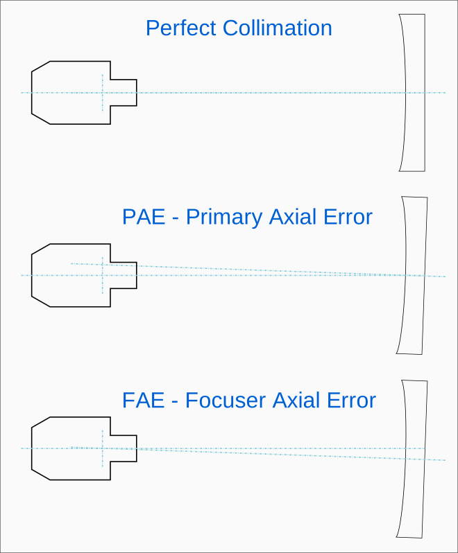 Primary Axial Error — PAEThe Primary Axial Error or PAE is the distance between the primary mirror’s optical axis and the axis of the focuser (or eyepiece) at the focal plane inside or just outside the eyepiece. PAE means that the primary mirror’s optical axis does not pass through the center of the eyepiece’s field of view. PAE is corrected by tilting the mirror in its cell with the three collimation bolts. The acceptable limit for this error has been derived from considerations of wavefront errors and depends strongly on the telescope’s focal ratio. The tolerance scales with the cube of the focal ratio. PAE = (0.005 mm) × F³ This gives the following tolerances:
The simulated star images shown later in the article will validate the numbers in the table. In practice, the easiest way to detect and correct PAE is to use a Cheshire collimation eyepiece together with a center mark on the primary mirror. By carefully aligning the reflected image of the Cheshire aperture with the center mark, it is not difficult to achieve sub-millimeter accuracy in PAE. Focuser Axial Error — FAEThe Focuser Axial Error or FAE is the distance between the focuser (or eyepiece) axis and the center of the primary mirror, measured at the mirror’s surface. FAE means that the focuser axis does not point toward the center of the primary mirror. FAE is corrected by adjusting the tilt of the secondary mirror using its collimation bolts. (Alternatively, the focuser itself could be tilted, but most telescopes do not allow for this adjustment). In practice, the easiest way to detect and correct FAE is to use a laser collimator in the focuser together with a center mark on the primary mirror. The secondary mirror orientation is adjusted to bring the laser beam as close as possible to the center mark. Several formulae for acceptable FAE values can be found in the literature. The original formula, reportedly valid in the absence of coma correction, gives a tolerance as a function of the primary mirror diameter D: FAE = 0.034 × D In other words, the FAE tolerance would be about 3% of the primary mirror diameter. Subsequent versions of this formula introduced reduction factors of 6 or even 12 to account for coma correction, resulting in tolerances as small as 0.5% or even 0.3% of the mirror diameter. These revised versions prescribe tolerances that are far too strict. In our opinion, the reduction factors are based on flawed reasoning. The results presented later in this article suggest that the FAE tolerances required for good image quality at the edge of an 80° eyepiece's field of view are significantly less stringent than the 0.5% and 0.3% rules would imply. The following table summarizes the findings. The values are based on a very conservative limit for spot diagram size, with spot sizes limited to 2 arcminutes at the edge of the field.
A more relaxed limit (even 5 arcminutes could be acceptable) would further increase the allowable tolerances. Three additional comments:
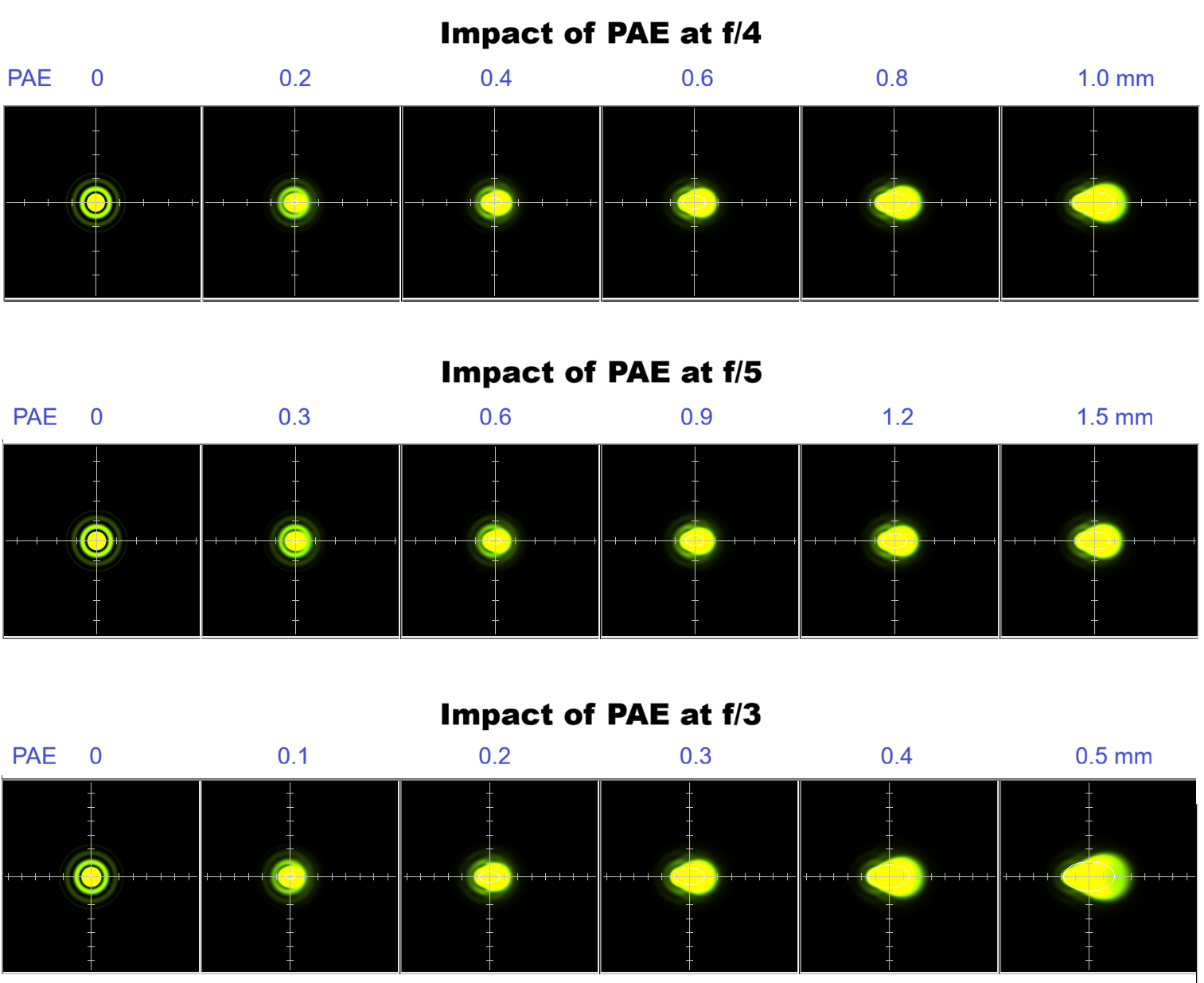
Practical Collimation ProcedureA practical collimation procedure involves two steps. First, minimize FAE by adjusting the tilt of the secondary mirror so that the laser beam hits the center mark of the primary mirror. Second, minimize PAE by adjusting the primary mirror’s collimation bolts until the Cheshire reflection is concentric with the primary mirror’s center mark. With this procedure, a small residual FAE will require a compensating tilt of the primary mirror to eliminate PAE. The tool used to correct PAE should be relatively insensitive to FAE. The Cheshire collimation eyepiece performs well in this respect. If some FAE remains and PAE is subsequently eliminated, the eyepiece will be centered on the primary mirror’s optical axis at the focal plane, but will be slightly tilted. This is exactly what would happen in a perfectly collimated telescope with a loose focuser that allows the eyepiece to tilt. RaytracingThe following sections show simulated star images and spot diagrams produced with the Eyepiece Designer, the software used to design the Houdini eyepieces. The optical model includes a perfect parabolic mirror and an ideal, high-power, coma-correcting eyepiece designed using hypothetical, idealized glass types. Raytracing PAEThe star images show the effects of PAE at the center of the field for focal ratios of 4, 5 and 3. The images are highly magnified to reveal the diffraction pattern. At the center of the field, we examine the distortion of the diffraction rings to determine an acceptable level of PAE. You can click on the image to open a full-size version.
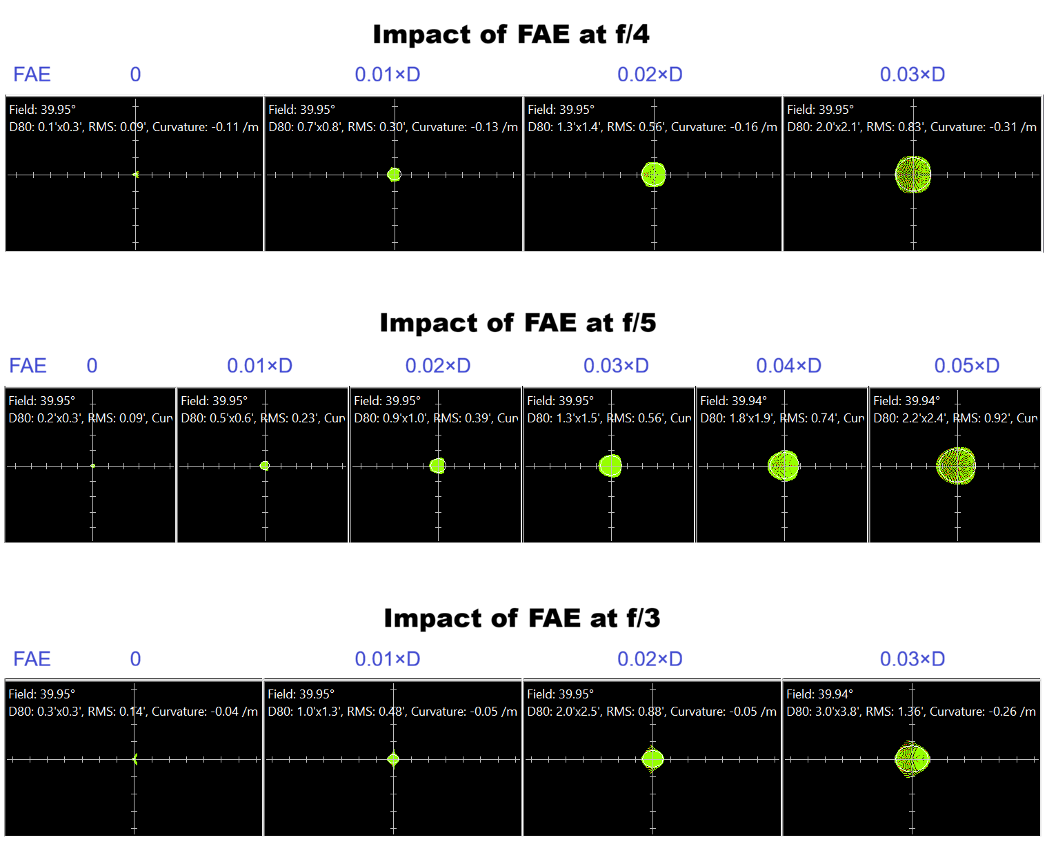
The PAE values increase from left to right and differ between focal ratios. They were chosen to produce approximately the same level of aberrations at each focal ratio. The first two columns show zero or low PAE values that would be acceptable. The aberrations become clearly visible from the third or fourth column onward. The results agree very well with the PAE formula given above and provide visual confirmation of the tolerances of 0.3 mm, 0.6 mm and 0.15 mm at focal ratios of 4, 5 and 3, respectively. Raytracing FAETo evaluate the effects of FAE, we assume that the collimation procedure described above has been followed and that the final adjustment with a Cheshire eyepiece has tilted the primary mirror as required to eliminate PAE. As explained above, the resulting situation is similar to that of an eyepiece tilted in the focuser. The aberrations will be small at the center of the field and will increase towards the edge. At the edge of the field, spot diagrams are more useful than diffraction patterns for determining which level of FAE is acceptable. The spot diagrams are shown near the edge of the field of an 80° eyepiece, i.e. 40° off-axis. A conservative limit for the spot sizes is around 2 arcminutes, which is close to perfection for any real eyepiece. You can click on the image to open a full-size version.
The results suggest that the following FAE tolerances produce excellent spot sizes at the field edge:
Using a 2-arcminutes spot size at the edge of the field is very conservative. If less-than-perfect image quality at the edge of the field is acceptable, these tolerances could be relaxed further.
Clear Skies! Robert Houdart
| ||||||||||||||||||||||
|