|
||||
IntroductionWhen considering how to design coma correcting eyepieces, I started from the expectation that the number of elements in the modern widefield eyepieces – typically 7 to 10 – would allow the coma correction to be built-in without adding new elements, and without adding significantly to the cost of the eyepieces. To test this hypothesis, I created an eyepiece designer application. I had already written some ray-tracing and optical system visualization code back in 1999, using Delphi, and I recently started revamping this code – literally 24 years after last touching it. I added an eyepiece quality scoring system and automated optimizer so that optical designs could automatically be improved. The result is an application called the “Cruxis Eyepiece Designer”. The goal of the Cruxis Eyepiece Designer is to optimize eyepieces by adapting the positions and powers of the optical surfaces, and selecting the best glass types, so that an overall “eyepiece quality score” is optimized. For each configuration the Eyepiece Designer traces many thousands of rays at various wavelengths. Usually red, green, and blue rays are used, but any combination of colors is possible. Rays are traced from the objective (a parabolic mirror or a perfect flat-field objective) towards the eyepiece. Behind the eyepiece, at the exit pupil, the direction and distribution of the rays coming out of the eyepiece are converted to a spot diagram as the human eye would see it, allowing for some limited focus accommodation of the human eye. The spot diagram, magnification, eye relief, curvature and vignetting for a series of field angles (typically 10 field angles to cover the whole field) are combined and weighted into a single score that expresses the “quality” of the eyepiece design. Eyepiece Quality ScoreThe quality of a modern eyepiece is a combination of several factors.
The Eyepiece Designer takes into account all these parameters with configurable weights so that one can easily nudge the design towards any target. The final solution will be the best compromise of all the factors above – by adapting the various scoring weights the application can force a design to go towards being smaller or cheaper, have more eye relief, less AMD, less curvature or tighter spot diagrams. The optimization uses a Monte Carlo approach with random changes applied to every optical surface to move the optical design towards a better quality score. The Eyepiece Designer uses the two main glass catalogs (Schott and Ohara) and can improve the eyepiece by selecting different glasses. You can filter the glasses on their relative price and their transmission in green and blue. Typically about 40 glass types from are considered in the optimization process. Compared to generic optical system design solutions like Zemax or Oslo the Cruxis Eyepiece Designer adds the specific know-how about eyepiece quality directly into the optical design evaluation, so that the automated optimization takes into account all factors that matter for an astronomical eyepiece and steers towards a design that will work. The Eyepiece Designer can scale eyepieces to different power or field targets. For example, starting from a good 12 mm eyepiece it's easy to create an eyepiece line from, say, 8 mm to 18 mm. Or starting from a 100° design it's easy to scale down to 85° field of view. User InterfaceThe application looks like the following: 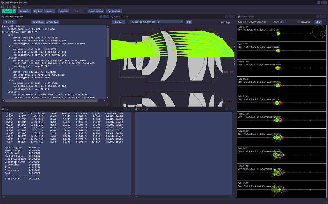 The screen shot shows a design for a 16 mm 100° eyepiece in a 300 mm f/4 Newtonian telescope. The Eyepiece Designer uses a simple text file to describe the optical system and the optimization control parameters. There are different sections for the optical layout (lens position, thickness, curvature, glass type) and for the optimization settings. The settings contain various parameters including the weights for the Eyepiece Quality Score, for example:
Settings
    TargetPower=75 MultiCPU=1
    TraceAngle=0.667 TraceSteps=9
    PencilType=HexaPolar Wavelength=RGB
    RaysGreen=1800 RaysRed=600 RaysBlue=600
    SpotScore=1 PowerScore=4 PowerVarScore=0.4
    EyeReliefScore=0.0002 EyeReliefMin=17 EyeReliefMax=20 EyeReliefUsable=0
    SaepScore=0.05 SaepAllowed=1.17
    CurvatureScore=0.003 CurvatureAllowed=0.6
    DistortionScore=0.01 VignettingScore=0.01
    LengthScore=0.00001 MassScore=0.001 CostScore=0.001
    OptDeltaCurvature=0.0002 OptDeltaPosition=0.1 OptDeltaRadius=0.2
    OptFixedPct=70 OptShiftAllPct=2
    MinimumEdge=2.5 MinimumAir=0.1
    GlassStart=5 GlassBrand=Schott GlassMaxPrice=3.6 GlassSkipDuplicate=1
    GlassMinTransm546=0.99 GlassMinTransm460=0.975
The first output for a single configuration is a table of spot circle sizes, eye relief, curvature, vignetting, and radial and tangential powers at the various field angles. Usually 10 field angles are analyzed to cover the whole field. Below the results for the 16 mm 100° eyepiece at f/4: Angle Field Spot Circle RMS Relief Curvature Vignet Power rad/tan 0.00° 0.07° 1.0'x 1.0' 0.42' 19.49 0.242 /m 0.00% 74.86/ 74.86 0.07° 5.55° 1.1'x 1.2' 0.45' 19.43 0.288 /m 0.00% 74.88/ 74.75 0.15° 11.10° 1.1'x 1.6' 0.52' 19.28 0.415 /m 0.00% 74.94/ 74.42 0.22° 16.66° 1.2'x 2.0' 0.64' 19.02 0.592 /m 0.00% 75.04/ 73.87 0.30° 22.22° 1.2'x 2.5' 0.77' 18.65 0.771 /m 0.00% 75.21/ 73.10 0.37° 27.80° 1.4'x 2.9' 0.93' 18.17 0.898 /m 0.00% 75.39/ 72.13 0.44° 33.40° 1.7'x 3.5' 1.14' 17.58 0.930 /m 0.00% 75.45/ 70.92 0.52° 38.97° 2.1'x 4.0' 1.31' 16.92 0.869 /m 0.00% 74.96/ 69.47 0.59° 44.48° 2.5'x 4.7' 1.51' 16.30 0.774 /m 0.00% 73.27/ 67.71 0.67° 49.83° 2.7'x 4.8' 1.60' 16.46 0.291 /m 13.11% 71.89/ 65.64These results are then combined in the Eyepiece Quality Score, like in the following: Spot Diagram 0.002702 Power Target 0.000014 Eye Relief 0.000097 SA Exit Pupil 0.000032 Field Curvature 0.000023 Distortion-AMD 0.000024 Vignetting 0.000066 Size 0.001125 Glass mass 0.000476 Cost 0.000867 ========================= Total Score 0.005426The scores are in fact penalties, so lower scores are better. PerformanceA typical ray trace of a system will consist of 3000 rays (1800 green, 600 red, 600 blue) for 10 different field angles, in other words 30,000 rays are traced to compute a single Eyepiece Quality Score. On a modern CPU the application can perform about 10 to 15 million ray traces per second and evaluate the Eyepiece Quality Score for about 400 layouts per second. Optimizing an eyepiece layout without changing its glass types is very fast, it will typically take less than a minute. On the other hand, optimizing the glass types is very lengthy and can take several hours, processing millions of configurations. | ||||
|