|
Mirror box of the 110 cm Cruxis telescope
This page discusses the mirror box for the Cruxis telescope.
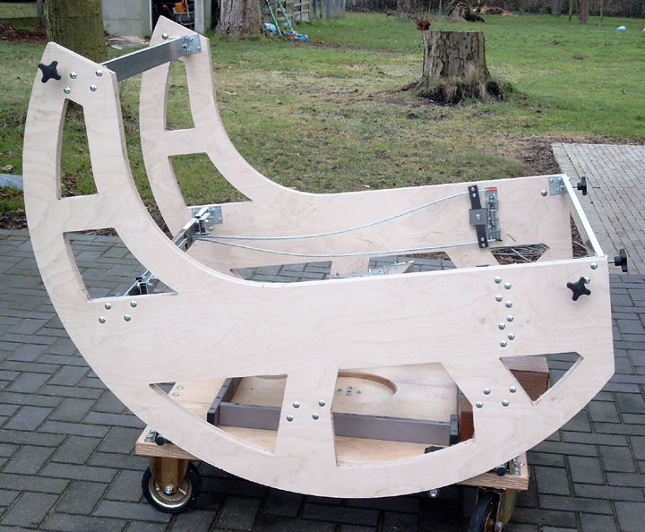
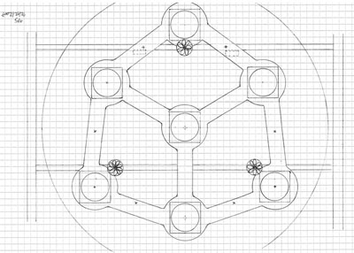
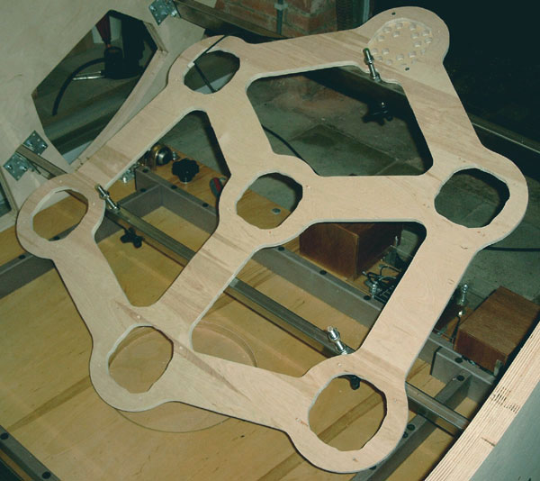
- Mirror box design
- The mirror box uses an open design that maximizes the air circulation and cooling of the mirror.
The two sides of the mirror box also serve as altitude bearings that ride on the rollers of the alt-azimuth platform.
They're made of 36 mm (1.5") thick plywood sheet. The radius of the altitude bearings is 780 mm (30.7").
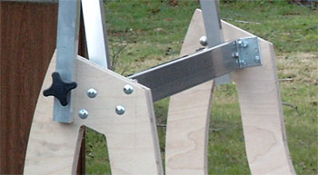
- The sides are connected by 5 rectangular 60x20x2 mm steel beams (2.4"x0.8"x0.08"). The two lower beams support the mirror cell.
- An overview of the weight of the main parts:
| Side walls (36 mm plywood) | 27 kg | 60 lbs
| | Cross beams (60x20x2 mm steel) | 15 kg | 33 lbs
| | 54-point Mirror cell | 13 kg | 30 lbs
| | Mirror edge support | 2 kg | 4 lbs
|
In total about 57 kg (127 lbs), without counting the primary mirror's 125 kg (270 lbs).
- Mirror Cell
- Some images of the 54-point mirror cell, see the Mirror Cell page for more detailed information.

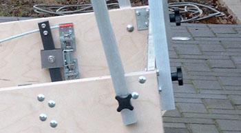
- The double cable sling edge support:

- Truss tube connections
- Four truss tubes connect to the mirror box near the optical surface, four other tubes connect near the top of the side bearing.
See the Truss Frame page for more detailed information.
- Finite element analysis of the Mirror box
- To validate that the altitude bearings do not significantly bend under the weight of the mirror box, a finite element analysis has been run.
Below a plot the finite element model. Move the mouse over the image to see the deflected shape when the telescope points at 3° altitude.
The deflection amounts to about 0.2 mm (0.01") and is magnified 250 times in the plot.

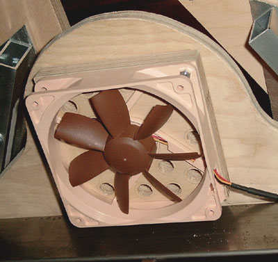
- Ventilation of the primary mirror
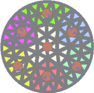 
- The primary mirror will be ventilated by 7 vibration-free and very quiet 120 mm fans at the back of the mirror.
Each fan blows into a header that feeds 18 tubes giving in total 7 times 18 = 126 tubes that blow air on the mirror.
Each of the 108 cells of the primary mirror will have its own feeding tube.
The goal is to avoid hot pockets in the cellular structure of the mirror.
- The remaining 18 ventilation tubes are available for removing the boundary layer from the front surface of the mirror, if this would be required
at a later stage.
| |