|
||||
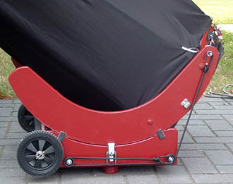
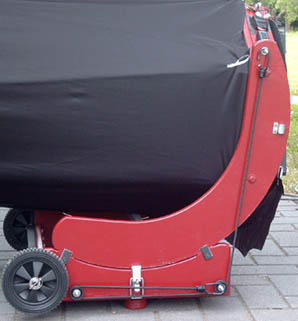
This page discusses the implementation of spring counterweights on Dobsonian telescopes, and presents an Excel sheet for computing the optimum spring properties for a particular configuration. An actual example of a bungee cord counterweight on a 16" f/5 scope is shown in some detail. I wrote this article back in June 2009, but never came to publish it. The contents still appears relevant and useful in October 2020. So here we go! Introduction to Spring CounterweightsWith the evergrowing number of useful telescope accessories like 2" eyepieces, barlows, coma correctors, binoviewers, filter slides or video cameras, keeping the telescope's Optical Tube Assembly (OTA) balanced can become a problem. On Dobsonian telescopes the heavy accessories near the eyepiece can make the OTA drop when observing at low altitudes, or can hinder the telescope's movements. When pushing the tube up you have to overcome the imbalance before the telescope starts moving, which can result in jerky displacements. The standard solution for top-heavy telescopes is to add counterweights at the bottom of the OTA, near the primary mirror. Unfortunately every pound added at the eyepiece needs to be compensated by a much larger weight at the mirror box. In typical Dobsonian telescopes a 1 kg binoviewer requires about 4 kg of counterweight at the bottom. A surprisingly effective alternative is to add one or several springs to keep the OTA balanced, a so-called "virtual counterweight". With some optimization of the spring properties one can produce designs that behave nearly exactly like an actual counterweight... but without the added mass! Spring counterweights are affordable and easy to install - especially if you use bungee cord as spring. Bungee cords are readily available in most hardware stores and are perfect for this use: cheap, light and replaceable. You can change the "weight" of the virtual counterweight by selecting a bungee cord with different stiffness. A Bungee Cord Counterweight on a 16" DobsonianA picture of a home-made 16" f/5 telescope with spring counterweight. The solution consists of a 6 mm
bungee cord about 750 mm long, two 32 mm pulleys and 3 stainless bolts with lock nuts that can be found
at any hardware store at a total cost below 5 Euro.
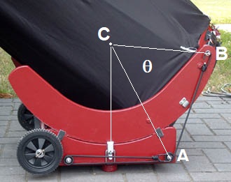
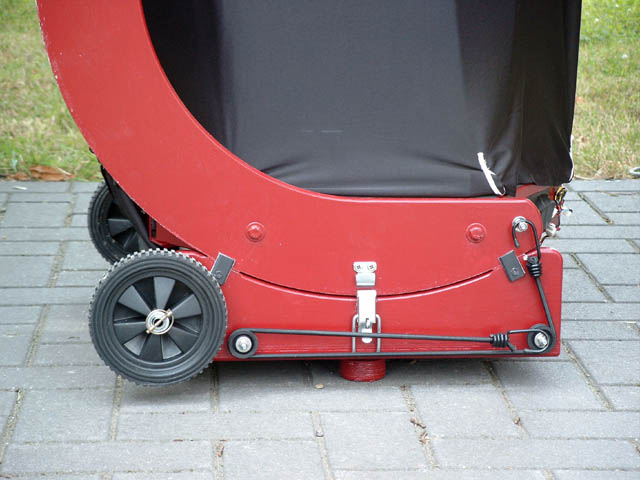 The ingredients: 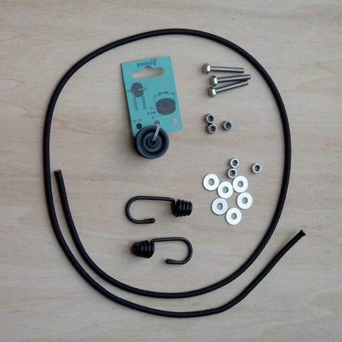 The bungee cord is attached to a bolt on the altitude trunion and runs via the two pulley wheels to an attachment bolt on the rocker box. The second wheel is only required to give sufficient length. When the telescope is lowered, the bungee cord is stretched and pulls at the mirror box.
  Does this system really mimic a normal counterweight from zenith to horizon?
Theoretical analysisThe force and rotation moment (force multiplied by perpendicular distance) that act on the altitude trunion can be computed with some basic trigonometry.
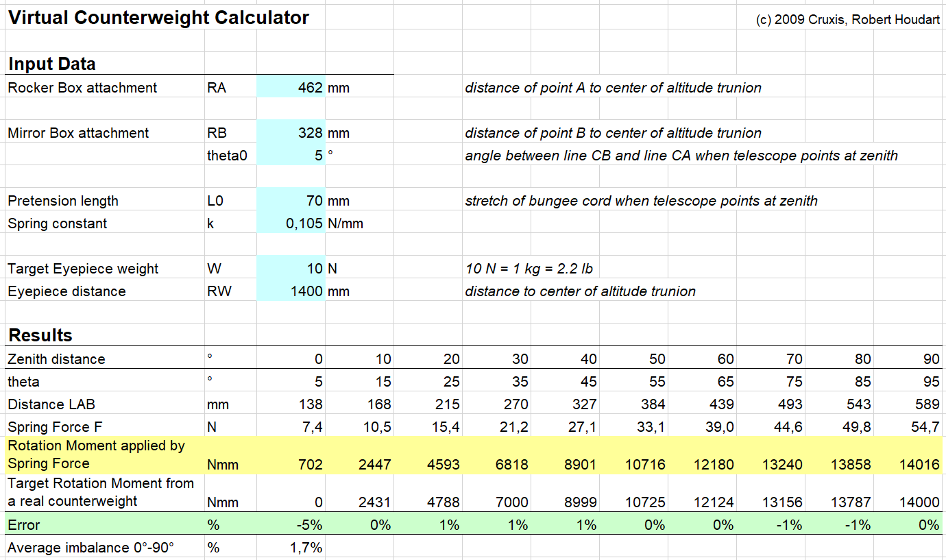
Determining experimentally the bungee cord spring constantIt's very easy to measure the spring constant of your bungee cord. Hang an object of known weight at the end of your bungee cord and measure the elastic elongation. The stiffness is the ratio between weight and elongation. For the bungee cord of the 16" telescope I used two boxes of milk (2.1 kg mass = 20.6 N weight) and measured the displacement as 280 mm. Spring stiffness is then 20.6 / 280 = 0.075 N/mm. The Excel sheet above shows that a spring stiffness of 0.105 N/mm would balance a weight of 1 kg at the eyepiece, so this spring should be the equivalent of 0.075/0.105 * 1 kg = 0.7 kg at the eyepiece. The actual 16" scope uses a pretension length of 80 mm - very close to the optimum value of 70 mm. Calculator for computing optimum spring propertiesYou can download the Excel sheet shown above. Adapt the position of your attachment points, select which load you want to compensate at the eyepiece, then experiment with the spring pretension length and spring constant to find the solution that is the best match. Some further thoughtsIdeally you should install a spring counterweight on both sides of the rocker box, so that the resulting forces are perfectly symmetrical. In practice having the spring only at one side works well also. It's very easy to modify the virtual "counterweight" of the system by using a different bungee cord. If you plan on using heavier equipment near the eyepiece, just switch the cord (takes less than 30 seconds) and you're set. I usually carry a somewhat thicker/stiffer bungee cord when I intend to use a binoviewer. This bungee cord is actually equivalent to 6 kg of counterweight at the back of the scope! The versatility, ease of installation and low cost of this system are truly great features. It simply works!
| ||||
|